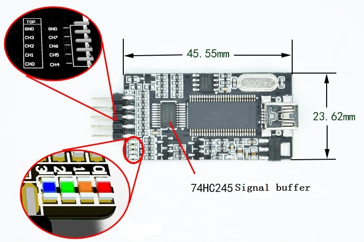
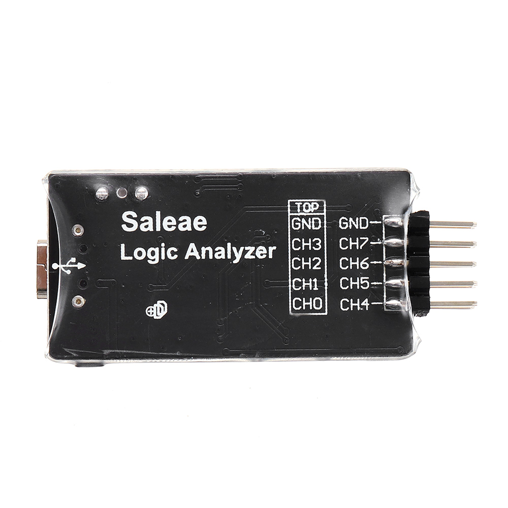
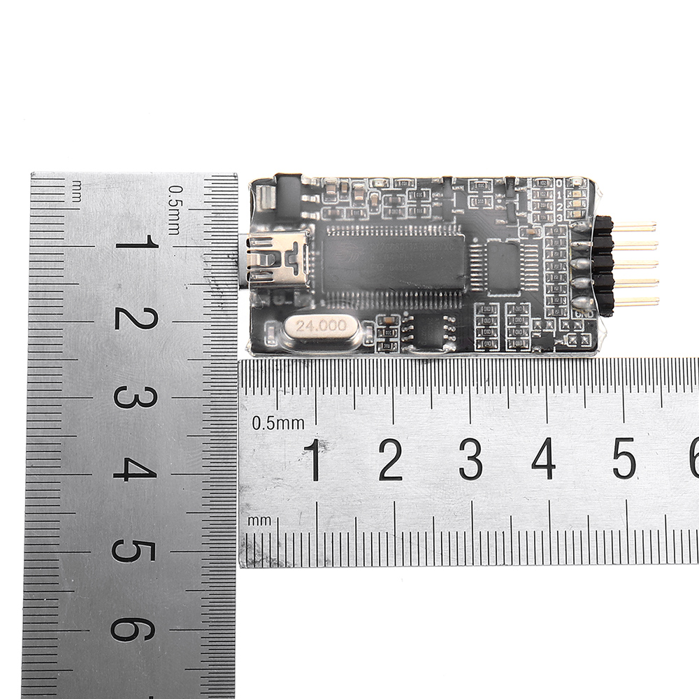
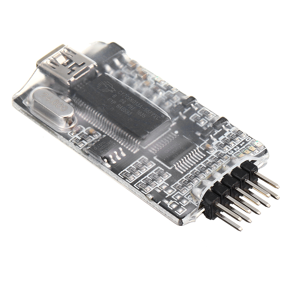
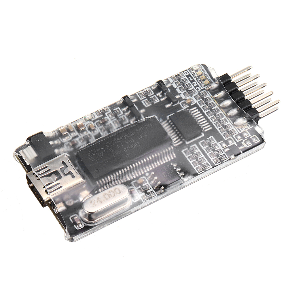
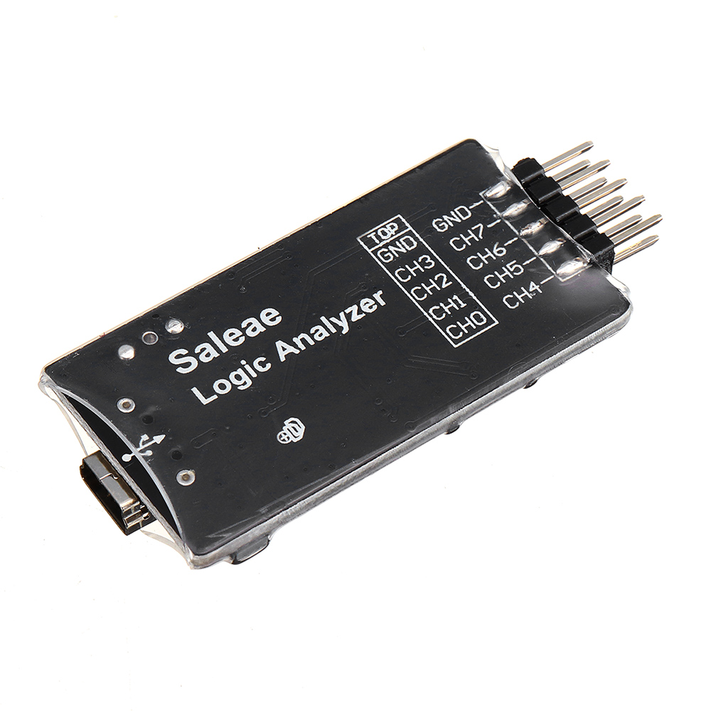
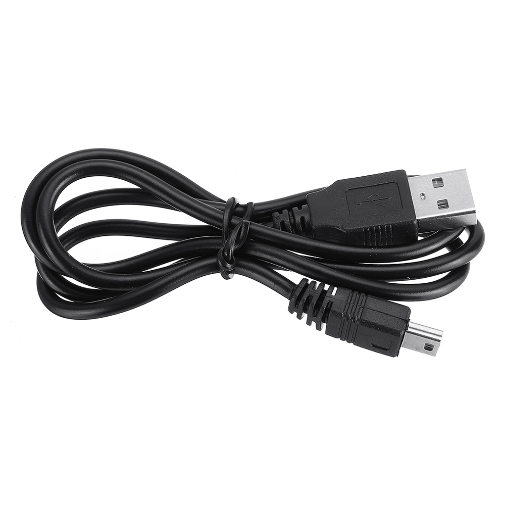
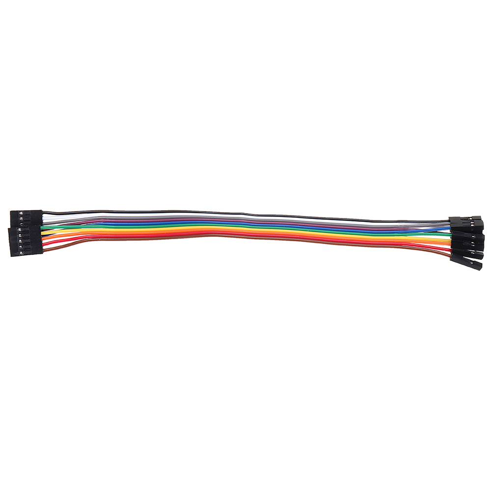
1. Signal input interface for the upper and lower rows of interfaces, the previous ones used 0246, 1357, wave arrangement, the order of wiring is up and down, which is very inconvenient; this logic analysis board changes the upper row to 0123 , the lower row is the order of 4567, which is simpler and not easy to make mistakes. Equipped with a 5pin cable, the 5th pin is grounded. In practice, it is most used to debug I2C, SPI, UART, etc. Generally, only the first four channels are used, and there is no extra thread, the wiring will become more concise and beautiful;
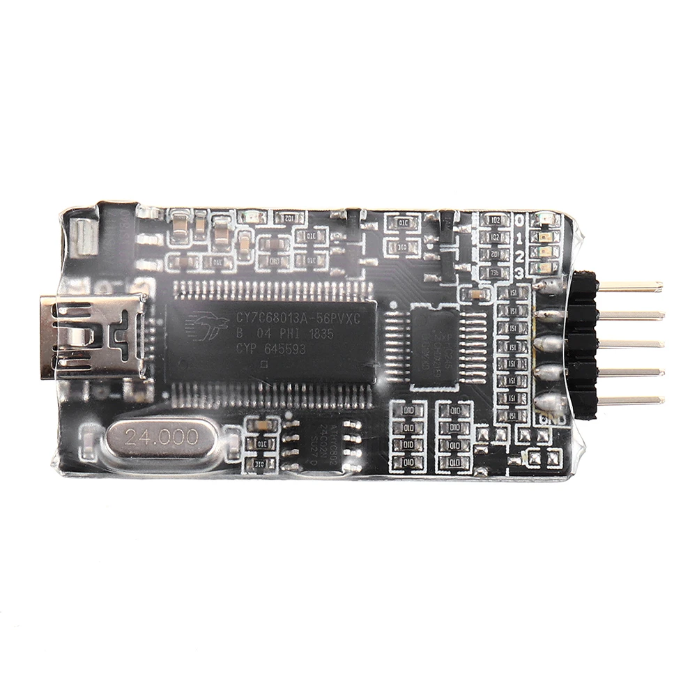
2. In the most commonly used channels 0-3, adds four color LEDs of red, orange, green and blue for level indication. For low-speed signals and communication process pauses, the LEDs can be seen flickering, which can be realized the function of the water lamp by MCU beginners with the smallest system board.
Specification:
Color: black
Applicable scenarios: single chip
Size: 56x23x5mm
Input mode: DC coupling
Storage capacity: 10GB
Bandwidth: 24MHz
Storage depth (bits/CH): 10240MB
Maximum measurement channels: 8
Maximum measurement input voltage: 5V
Operating system: WIN10, WIN7, WIN8, osMac, Linux
Feature:
1. Add 0123 channel indicator
2. Rearrange the order of input channels
3. 01234 channel input on the upper row, 4567 channel input on the lower row
Package included:
1 x Logic Analyzer
